I ran out of time last update designing the serial bus. One end of the wire harness will need to be located in the rear of the case, and
be a female connector. So a standard serial cable can be plugged into it.
I'll harvest one from a dead 1541 I have.
I have everything for the
serial bus; next...
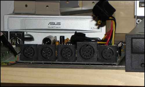
The parallel connector is a tough one. It's the largest DIN plug in the pic. One approach is to steal the connector from the HD board and use it at the
back of the case. I rather not mod the CMD or other more rare stuff. I'll chop a 1541 in half for the fun of it.
The other solution is to provide a hole for
the cable in the back of the case somewhere.
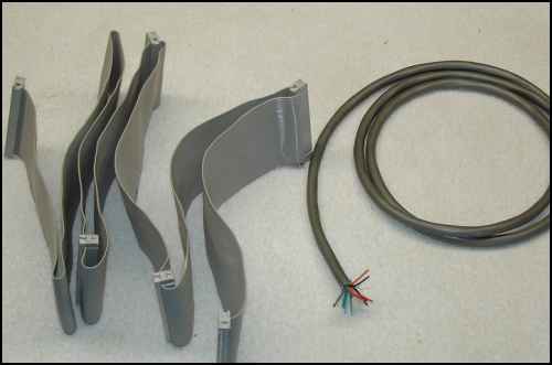
Back from the electronics surplus store. Picked up a longer SCSI cable and a control cable for...
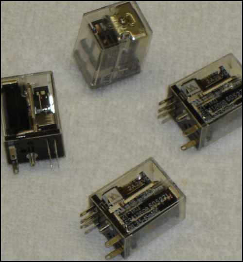
...Relays.
Rated 1A @ 125VAC and 2A 28VDC, they'll do nicely for controlling the two power voltages.
Even though they're built
like tanks, I picked up a spare to send along to Alan.
I'm still undecided on how to wire the power switches. The relays really only move the mass of wires
from one area of the box to another and is a lot of work to do so.
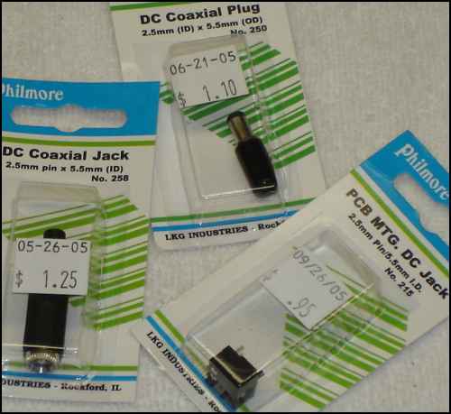
Connectors for the 9VDC
Meanwhile, I'll work on the serial bus.
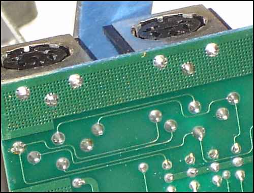
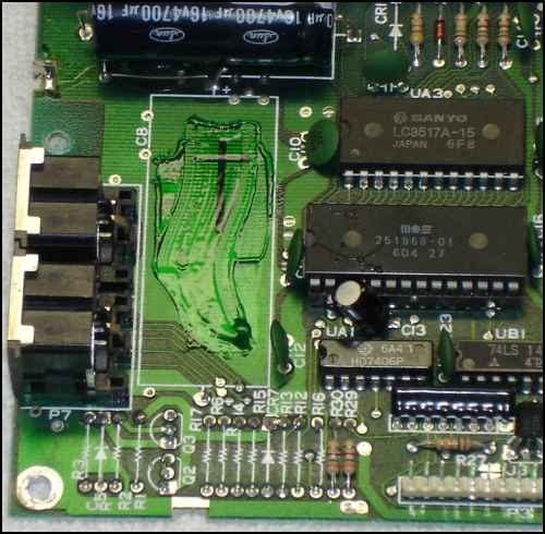
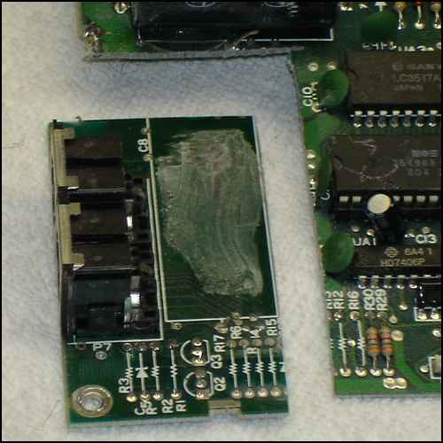
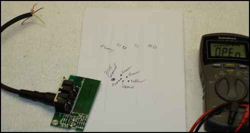
Here is a dead '41 board with all the electronics removed from around the connectors I need.
Grab the hacksaw, and cut away.
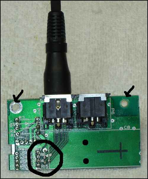
The cable for the bus gets attached to the points in the circle. the two black dots are where I'll drill holes for a
zip-tie; for cable strain relief.
The two arrows point out the mounting holes.
Two connectors means the box can be daisy chained like any serial device.