Last update, i ran out of time. I had wanted to do a rough walk through of the remainder of the project.
The old timey electronics
place isn't open on weekends, so I need to make a list today. I'm planning to work at all weekend. See how much I can get done, without forcing it.
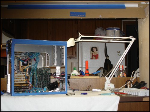
I look over at the beast...
We need a 4 wire cable with at least a 18 automotive wire and #14 wire would be best. One for each switch and 3 feet long.
Better too long than too short; wire stretchers are hard to find.
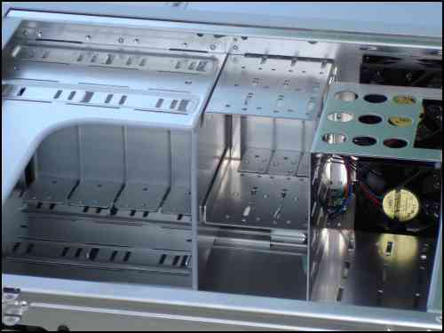
The CMD hard drive has it's controller board at the top of the 5 1/2 bay (far left). The drive goes in the 3.5 drive bay (far right). So I'll
get some long 50 pin SCSI cable. By the time it's rounded and wound around in the box, we need 22/24 inches and the least connectors, since I'll remove them
for rounding.
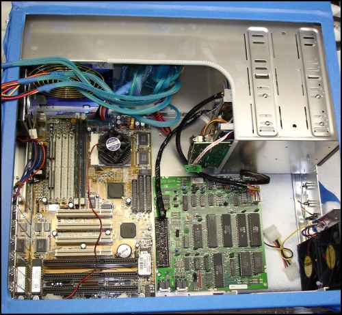
The HD runs on 9VDC, so we need a male & female power connector, like an extension cord, from where the wall wart connector meets the back
of the box, to the HD PCB.
Everything else will be powered by the PC supply.
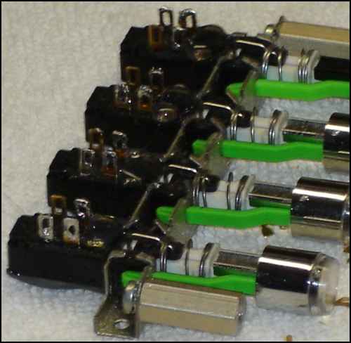
Now, let's plan the serial bus. From the 1571 board, up the back side of the drive bays, I'll make a wire harness to connect to each drive.
Not a daisy chain, but a harness.
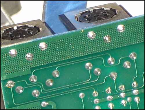
You can see both serial connectors are connected directly. There is no processing of the signal. So we are not limited to a linear daisy chain,
but can use a star design for the bus.