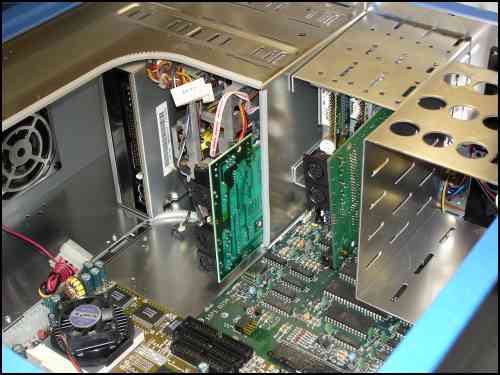
We left off last update with the mounting of the parts in the 3.5 bays. Now I go on to the 5.25 bays.
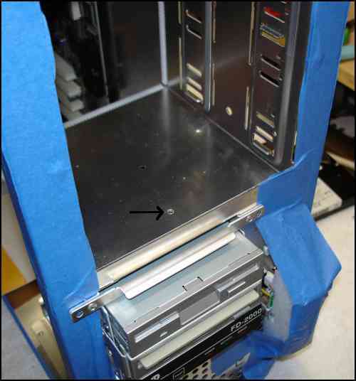
The hole for mounting the 1541 II PCB.
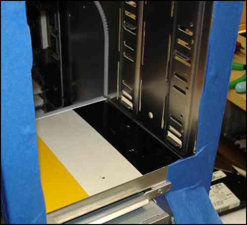
The dense cardboard insulator.
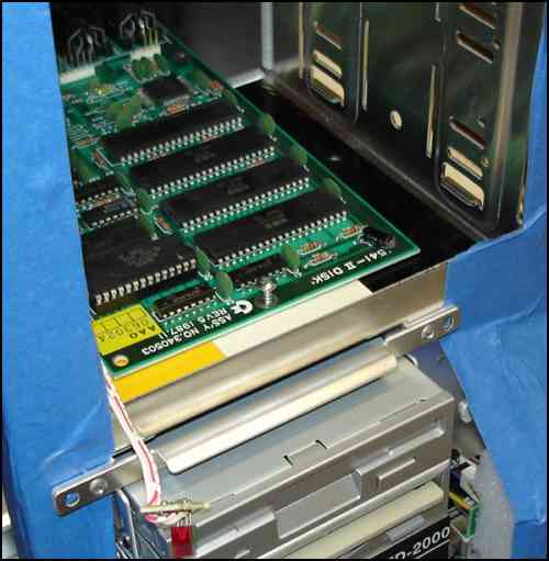
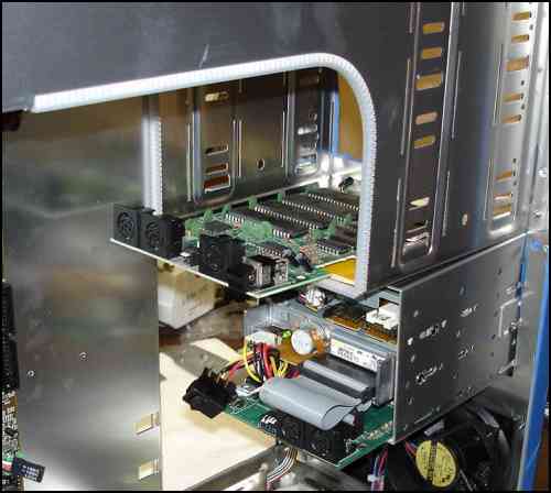
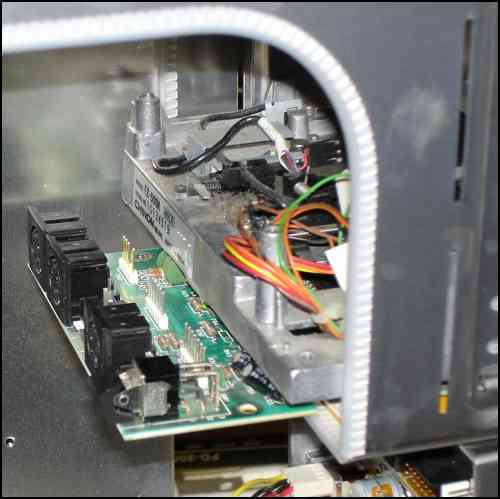
The PCB in place and the screw started.
A view from the back side.
The drive mech in place. Just enough room. The connecting cables will attach with modification.
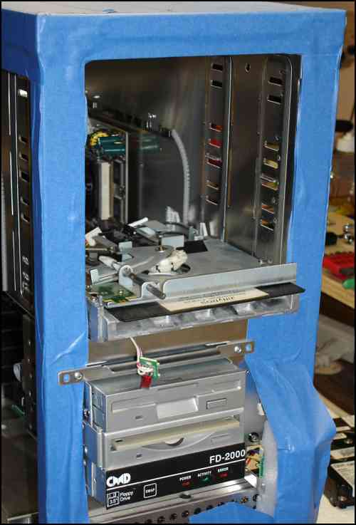
A view from the front with the drive mech in place. You can see the LEDs for power and activity which will be mounted in the face place.
I am going to use the blank face plates for the 5.25 drive mechs, like the FD 2000 in the 3.5 cage.
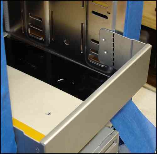
The face plate takes up space the drive mech needs. This will be a tough part of the mod. I will cut them shorter ( dotted line), and bend them to reach the drive cage just before the drive mounting area.