The next rail in place. This one holds one side of the drive cage.
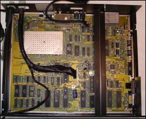
Next the rail between the two drive boards.
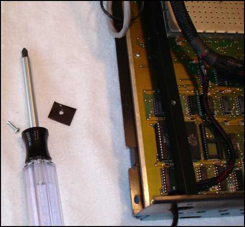
The last rail came out just a bit short, so this spacer is used to fill the difference.
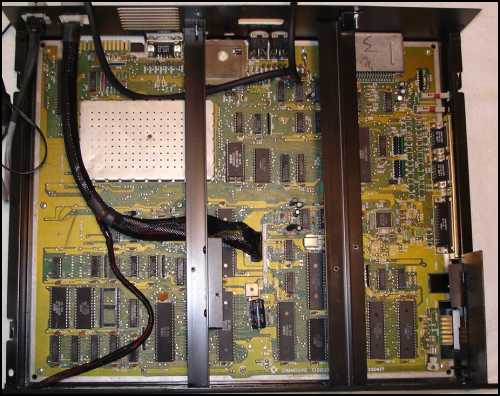
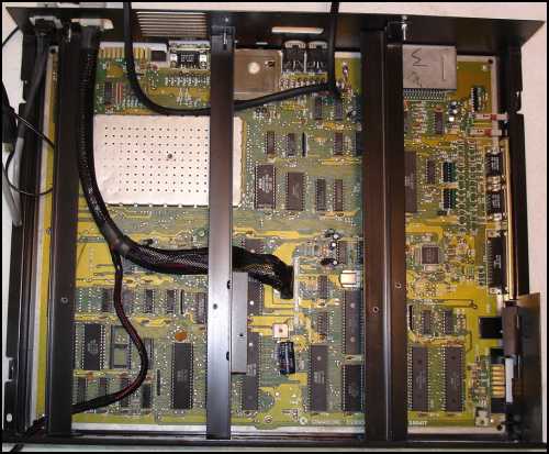
And the final rail is installed.
Next the drive cage with the drives installed is slipped in as far as it will go.
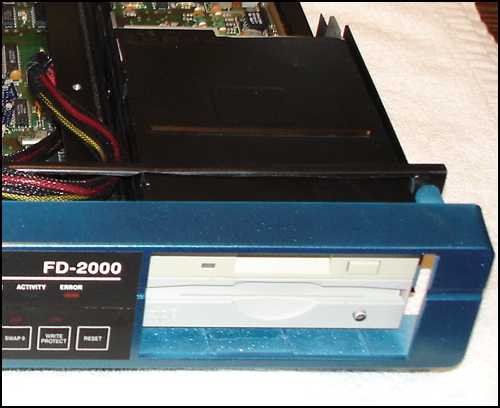
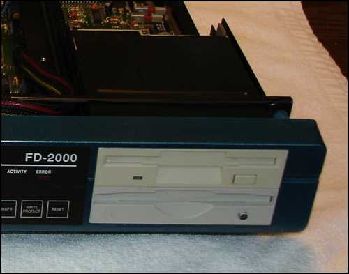
The face is put up to the case and the on light is installed.
The face is tilted up and screwed on.
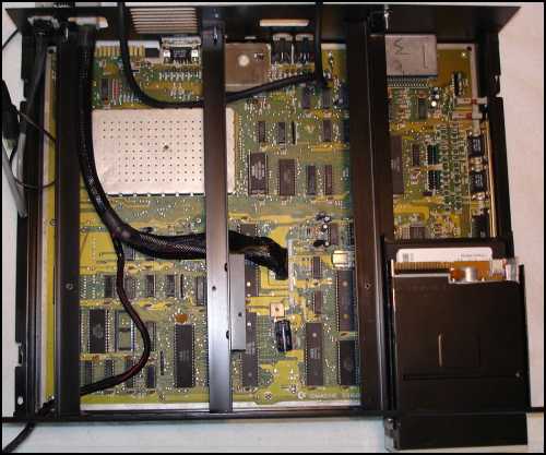
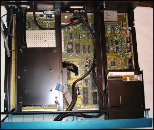
Here the drives are still back as far as they will go.
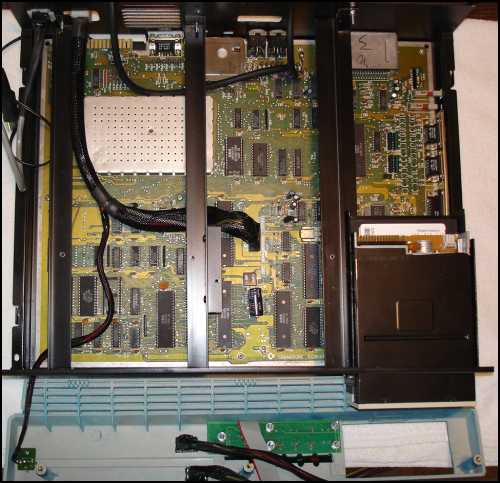
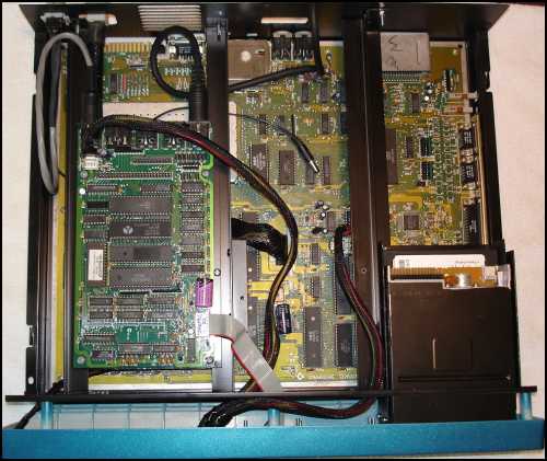
Now slide the drives forward.
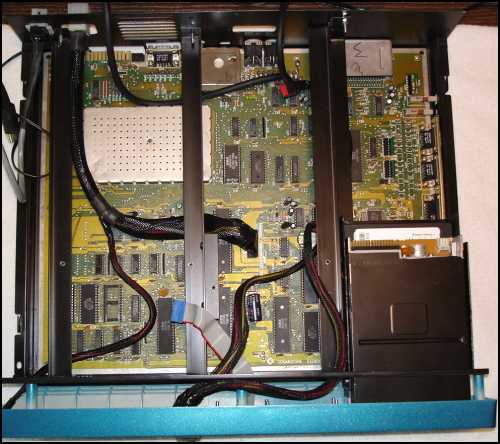
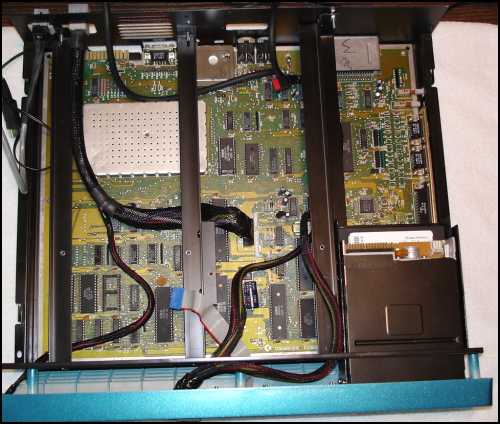
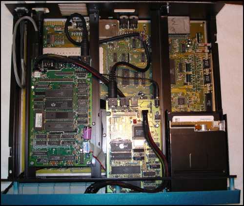
The drives in place.
Now the mounting plate for the CMD HD board.
Next the board and it's wiring.
The CMD FD is a little more tricky. First attach the mounting plate, and test fit the board. I'm looking for a good feel for the switch on the face. Adjust as needed. Attach wiring.
Here it is completed.
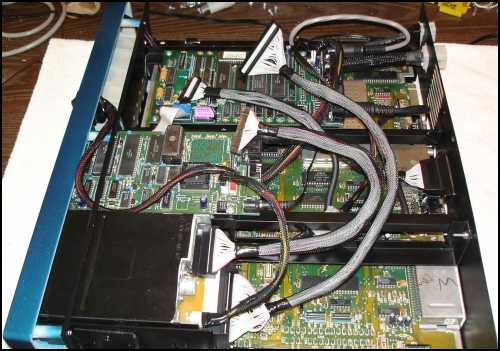
And now for the rounded ribbon cables. The boards headers aren't labeled with pin one.